Cisco Catalyst 8000v Cluster - Create
To create a Cisco Catalyst 8000v Cluster, follow the guided steps in the Evolution Platform console. Prepare the mandatory service-level values listed below before you start the provisioning wizard.
Step 1 - Select project
Select the project in which you want to deploy your virtual Edge:
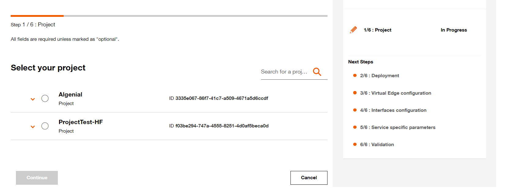
Select your project.
Step 2 - Deployment configuration
2.1 Name your Virtual Edge (This name will be displayed on the Virtual Network Edge dashboard)
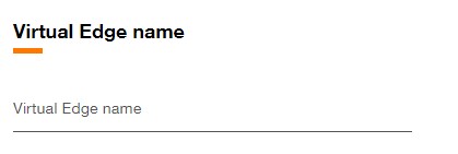
Set Virtual Edge name.
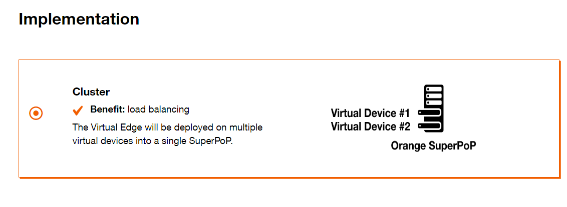
Select implementation mode.
Virtual device configuration
2.3 Fill the Virtual Device name (This name will be used as hostname for the virtual device).
2.4 Select the Orange POP which correspond to the location of POP.
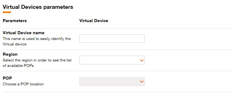
Fill Virtual Device Name, Region and POP.
For Dual topology, different POP can be chosen for each virtual Device.
For Cluster topology, the Virtual devices must be on the same POP.
Select Internet and MPLS Bandwidth for each Virtual Device.

Select Internet and MPLS bandwidth for the Virtual Device.
Step 3 - Virtual Edge configuration
3.1 Select the Software version.
Available software versions are :
- 17.12.3
3.2 Select the Virtual Device flavor.
Available flavors are :
| Standard | DPDK | |
|---|---|---|
| Small | 2 vCPU 4 GB Mem 64 GB Disk | 2 vCPU 4 GB Mem 64 GB Disk |
| Medium | 4 vCPU 8 GB Mem 64 GB Disk | 4 vCPU 8 GB Mem 64 GB Disk |
| Large | 8 vCPU 16 GB Mem 64 GB Disk | 8 vCPU 16 GB Mem 64 GB Disk |
- For Dual topology, different flavors can be selected for each Virtual device.
- DPDK (Data Plane Development Kit) is a set of libraries and drivers designed to acceler- ate packet processing and optimize performance in network applications. It provides a high-performance framework for managing network traffic at a low level, bypassing the traditional kernel network stack to enhance throughput and reduce latency.
Pay attention the use of an image with DPDK significantly increases energy consumption and therefore the associated carbon footprint.
3.3 Click on Continue button to continue the journey or click on Save button to save the current deployment configuration.
Step 4 - Interfaces configuration
Interfaces
The console presents interface configuration in numerical order. Typical steps per interface type:
- For #2 - MPLS-VPN interface add VLAN sub-interfaces (for example VLAN 101..108). For each VLAN sub-interface select the VPN Name and, if needed, the VPN role. You can also enable BGP on a per-VLAN basis using the Enable BGP option and provide AS prepend when required.
- #1 - Internet Interface - access and #4 - Internet Interface - core are Internet-facing interfaces; public IPv4 addresses shown in the console are platform-allocated outputs and do not require a customer-supplied public IP during standard provisioning.
- #3 - MPLS-VPN Interface - transport allows optional VPN selection and static route entries when required by your design.
Virtual device configuration
Cloud-init is automatically generated by the platform for this VNF. Custom user-data upload is not allowed for this blueprint.
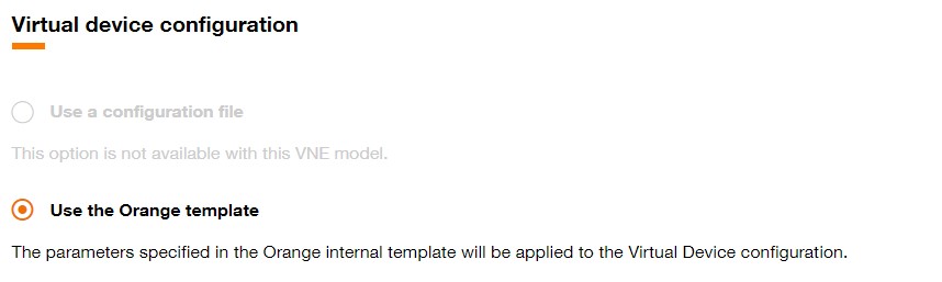
Virtual device configuration screen in the console.
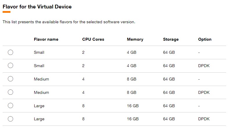
Select image and flavor for the virtual devices.
Step 5 - Service specific parameters
5.1 Fill in the following service parameters:
- VM AS number (VM1): AS number assigned to VM1 for BGP identification. The specification allows 2-byte and 4-byte AS numbers and provides numeric bounds. min 1, max 4294967295.
- VM AS number (VM2): AS number assigned to VM2 for BGP identification. The specification allows 2-byte and 4-byte AS numbers and provides numeric bounds. min 1, max 4294967295.
- Organization name: Enter the organization name that the platform should associate with this VNF instance. This value is required and is not updatable after creation.
- Vbond IP address or FQDN: Provide the vbond controller IP address or FQDN exactly as reached from the VNF. The portal validates the value against the specified pattern. pattern: ^([a-zA-Z0-9._-])63$.
- Site id: Enter the numeric site identifier assigned by your organization for this location. This value is required and not updatable after creation. min 1, max 4294967295.
- Password: Provide the administrative password to be set on the VNF during provisioning. The platform treats this value as secret and does not display it in plain text.
- System IP (VM1): Provide the IPv4 System IP for VM1 used by the SD-WAN control-plane. This is a mandatory provisioning parameter.
- Loopback1 IP address (VM1): Optional IPv4 loopback address for VM1. Provide it only if required by your SD-WAN design.
- UUID (VM1): Provide the VM UUID value required for provisioning. It is mandatory and not updatable.
- One time Password (VM1): Provide the one-time password as requested by the portal; this value will be treated as secret.
- System IP (VM2): Provide the IPv4 System IP for VM2 used by the SD-WAN control-plane. This is a mandatory provisioning parameter.
- UUID (VM2): Provide the VM2 UUID required for provisioning.
- One time Password (VM2): Enter the OTP when the portal requests it for VM2; the value is treated as secret.
5.2 Click on Continue button to continue the journey or click on Save button to save the current deployment configuration.
Step 6 - Validation
After clicking the Continue button, a page summarizing the characteristics of the Virtual Edge will be displayed.
This page is divided into several sections :
- Projects
- Deployment
- Virtual edge configuration
- Interfaces configuration
- Service specific parameters
At this stage, it is still possible to modify the characteristics for these sections.
One section is dedicated to display the Carbon footprint of the Virtual Edge :
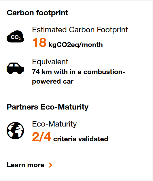
Carbon footprint for Virtual Edge.
Click on the Provision button to initiate the provisioning of the Virtual Network Edge.
You can also preserve the Virtual Network Edge configuration by clicking the Save and close button and the following toast is displayed.
In this case, you will find the Virtual Network Edge in designed state on the .
