Zscaler Private Service Edge - Create
Use the Evolution Platform creation wizard to provision a Zscaler Private Service Edge instance. During creation you provide service-level values (for example the ZPA provision key and device credentials), choose image and flavor, and configure VLAN sub-interfaces for MPLS connectivity.
Step 1 - Select project
Select the project in which you want to deploy your virtual Edge:
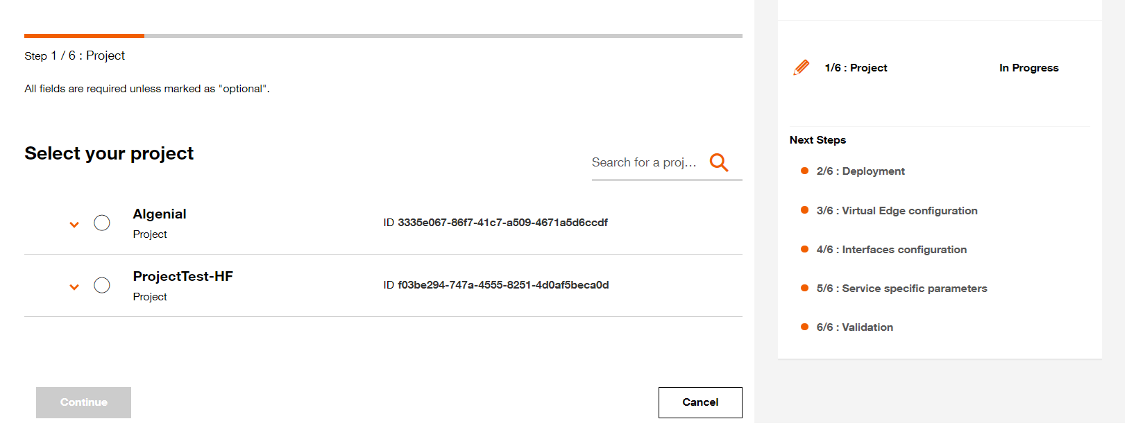
Select your project.
Step 2 - Deployment configuration
2.1 Name your Virtual Edge (This name will be displayed on the Virtual Network Edge dashboard)
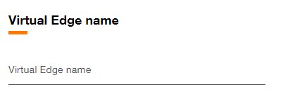
Set Virtual Edge name.
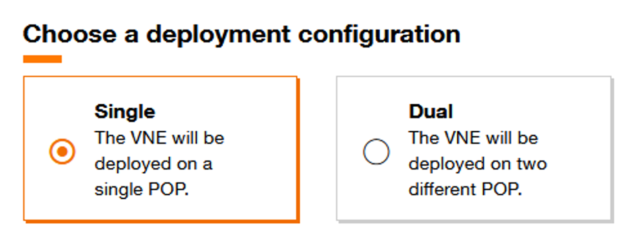
Select implementation mode.
Virtual device configuration
2.3 Fill the Virtual Device name (This name will be used as hostname for the virtual device).
2.4 Select the Orange POP which correspond to the location of POP.
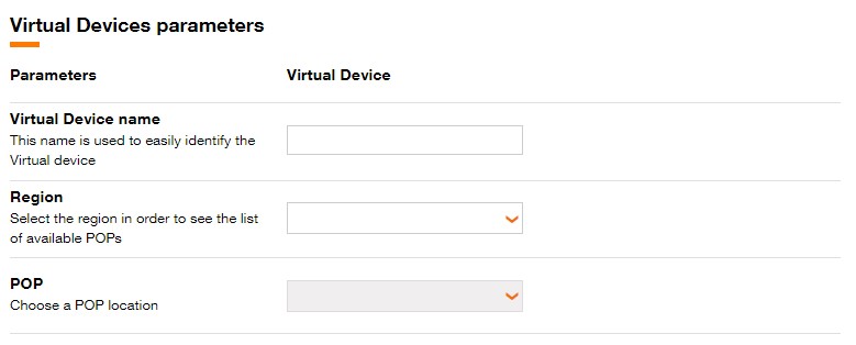
Fill Virtual Device Name, Region and POP.
For Dual topology, different POP can be chosen for each virtual Device.
For Cluster topology, the Virtual devices must be on the same POP.
Select Internet and MPLS Bandwidth for each Virtual Device.

Select Internet and MPLS bandwidth for the Virtual Device.
Step 3 - Virtual Edge configuration
3.1 Select the Software version.
Available software versions are :
- 9
3.2 Select the Virtual Device flavor.
Available flavors are :
| Standard | |
|---|---|
| Small | 4 vCPU 8 GB Mem 64 GB Disk |
| Medium | 8 vCPU 16 GB Mem 64 GB Disk |
- For Dual topology, different flavors can be selected for each Virtual device.
- DPDK (Data Plane Development Kit) is a set of libraries and drivers designed to acceler- ate packet processing and optimize performance in network applications. It provides a high-performance framework for managing network traffic at a low level, bypassing the traditional kernel network stack to enhance throughput and reduce latency.
Pay attention the use of an image with DPDK significantly increases energy consumption and therefore the associated carbon footprint.
3.3 Click on Continue button to continue the journey or click on Save button to save the current deployment configuration.
Step 4 - Interfaces configuration
Interfaces — what you must provide
Explain which interface values are customer inputs and which are allocated by the platform.
-
#1 - Internet Interface: the platform allocates a Public IP address and shows it in the provisioning results. No customer IP is required during creation for this interface.
-
#2 - Management interface: the platform allocates a Management IP address and exposes it in the provisioning summary. No customer IP is required during creation unless the portal explicitly asks for an allocation range.
-
#3 - MPLS-VPN interface: you must configure VLAN sub-interfaces and attach VPN entries. VLAN 101 is required; VLANs 102–108 are optional. For each VLAN sub-interface provide at least one VPN entry (VPN Name and VPN role). BGP on each VLAN sub-interface is optional.
Quick creation notes
- VM name: provide a valid hostname (used to identify the VM).
- Image: select the provided CentOS image.
- Flavor: choose std1.c4 or std1.c8.
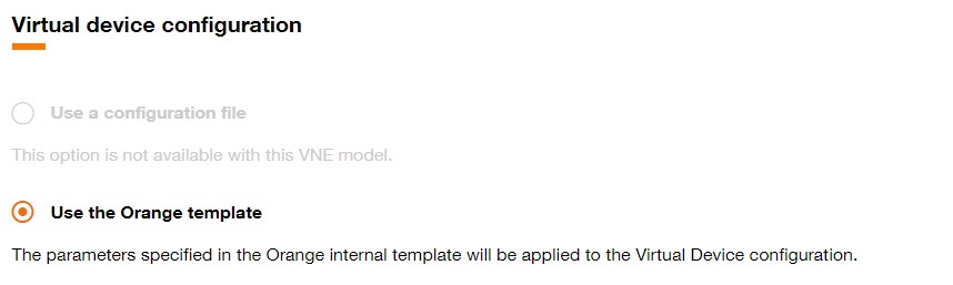
Virtual device configuration.
Step 5 — Service specific parameters (sensitive)
Provide service-level values required to provision the appliance. These fields are treated as sensitive by the platform and stored securely.
- ZPA provision key — mandatory, not updatable. Obtain this key from Zscaler and paste it into the creation form so the service-edge container can register to your Zscaler tenant.
- Admin password — mandatory, not updatable. Initial admin user password for the device image; keep it secret.
- Root password — mandatory, not updatable. Root account password set during provisioning; keep it secret.
- VM AS number — mandatory when BGP is used. Provide the autonomous system number for BGP peering when you enable BGP.
Do not paste real credentials in documentation or public places. Provide values in the portal fields during creation.
Step 6 - Validation
After clicking the Continue button, a page summarizing the characteristics of the Virtual Edge will be displayed.
This page is divided into several sections :
- Projects
- Deployment
- Virtual edge configuration
- Interfaces configuration
- Service specific parameters
At this stage, it is still possible to modify the characteristics for these sections.
One section is dedicated to display the Carbon footprint of the Virtual Edge :
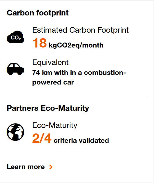
Carbon footprint for Virtual Edge.
Click on the Provision button to initiate the provisioning of the Virtual Network Edge.
You can also preserve the Virtual Network Edge configuration by clicking the Save and close button and the following toast is displayed.
In this case, you will find the Virtual Network Edge in designed state on the .
